Electrical system diagnosis and repair is tricky business to begin with. Parasitic drains, intermittent faults and inefficient/improper grounds are just a few of the ways technicians can get drawn down the wrong diagnostic rabbit hole. This was true even for vehicles from the turn of the millennium, when system design was simpler and there was less variation in approach from OEM to OEM. Today, many of the OEMs are taking unique approaches to system operation and design. This complicates things, making it more important than ever to master both the general principles of vehicle starting/charging system operation and the specific approaches used by the different vehicle manufactures. In this article, we highlight the diagnostic and repair challenges presented by specific OEM system/component/network designs, and wrap with two videos that are more generalist and back to basics in nature, dealing with the importance of the battery as the centerpiece of these systems.
Chrysler TIPM – Failure Modes and Repair
In what will be a relatively common theme in this article, Chrysler utilizes a Totally Integrated Power Modules (TIPM) that combines fuses, relays and module into a single master component to reduce their wiring load and simplify the power circuit. But, as Andrew Markel points out in this article from UnderhoodService.com, the TIPM can be difficult to diagnose, since it impacts so many of the vehicle’s systems. This could cause a technician to replace components, such as a starter or fuel pump, when it is actually the TIPM that is the root cause of the issue. As he states,
“The symptoms of a failing TIPM can vary depending on the vehicle. On one car, it might be an inoperative horn or wipers. For other cars, it might be a no-start condition and erratic instrument cluster operation. A failure can be seen by a no crank condition.”
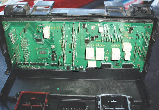
He suggests starting with a customer interview and attempting to recreate the issue. He also reminds that, since the TIPM is on the CAN bus, it is critical to confirm communication with connected modules and all components commanded by the TIPM, particularly the ones related to the customer complaint. He then outlines a general step-by-step diagnostic strategy to overcome TIPM-related issues. It is a great read. Check the article out here or click the above photo.
Toyota Fusible Block – What it Is and How to Replace It
Similar to Chrysler’s effort to reduce complexity in its power circuit, Toyota has switched from the approach of having many individual fuses inside the relay box (RB) to having an integrated component, the fusible block, that houses multiple fuses (as many as 10) inside the relay box. The trick is that, if any individual fuse within the assembly is blown, the entire fusible block must be replaced. The process of replacing the fusible block can be cumbersome and time consuming, costing much more than the cost of the component itself. It is so cumbersome, in fact, that Dan Marinucci needed three separate articles in Motor Magazine to cover it. Here are links to each:
October – Introductory Article
Combined, the articles provide a very thorough, deep dive into this service issue. This is a step-by-step tutorial, complete with photos to illustrate many/most of the steps. He has lots of great advice, including how to avoid issues with the fusible link to start with. For instance, as we have recommended in many previous articles, whenever you disconnect the vehicle’s battery, it is a best practice to secure and protect the positive charging cable to the battery – you don’t want to allow it to accidentally contact a vehicle ground. In addition, he specifically warns against trying to remove the fusible block using brute force, noting you could damage much more than just the fusible block. We definitely think it is worth your time investment.
Honda LIN Controlled Charging Systems
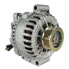
This one is a little different than the above two examples, since it covers a change in how components are controlled, rather than how they’re configured. For just over ten years, according to this article by Andrew Markel on Import-Car.com, Honda has deployed a local interconnect network (LIN) to allow the PCM to control the battery charging function, usually in tandem with a sensor at the negative battery terminal. This allows charging current and voltage to be dynamically controlled, with feedback from the sensor, which tracks numerous inputs that impact charging need.
Side note: We have addressed these battery-mounted sensors in previous articles in relation to both Ford and GM vehicles, specifically related to the importance of connecting the negative clamp of your jump starter or battery charger to a good vehicle ground. Connecting directly to the negative battery terminal will bypass this sensor, causing numerous issues in the battery management system.
This quick article addresses the general system design, how communication is managed and potential fault codes generated when non-conforming performance is detected.
“The PCM sets a target generating voltage in the range of 12.5- to 14.5-volts using the LIN line. If the output voltage does not match the commanded voltage for the engine speed, it sets a code that the voltage is too high or too low. DTC P0562 is for the charging system voltage that is too low. DTC P1549 is for the charging system voltage being too high. If there is no voltage coming from the alternator, code P056A will be set for No Charging Malfunction.”
Don’t Forget the Battery
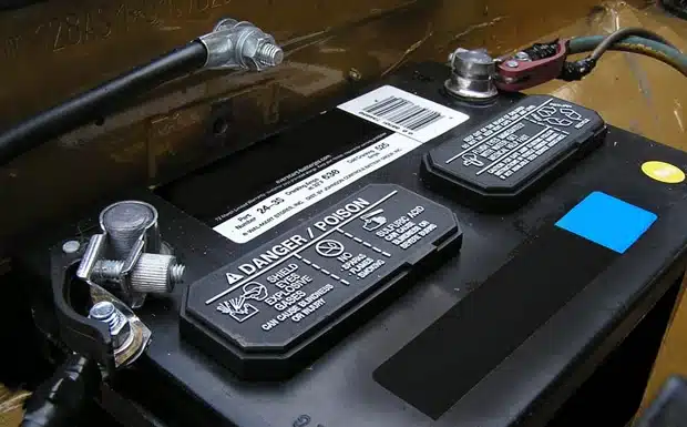
Yes, system designs have changed considerably over the last twenty years. What used to be relatively straightforward is now significantly more complicated, in terms of diagnosing the root cause of an electrical system/power failure. That said, many of the procedures and principles that have served technicians in good stead for decades still ring true. One of those key principles that is truer than ever is, “Start with the battery.” Here are two quick videos from Import-Car.com that provide two great, and different, examples of problems that started with the battery but could look like they really originated elsewhere.


That sums it up for this month. We hope you found these looks at specific system designs useful and that they added a few new tips or techniques to your diagnostic and repair toolbox. Is there a specific system that causes you outsized headaches and hassle? We love to hear from you. Please let us know in the comments below.