In these feature articles, we cover a lot of ground related to electrical system diagnostics. That’s because most of our products are used in response to or in prevention of an electrical system issue. We believe that gathering the latest intelligence and best practices around system diagnosis can be very helpful and time saving for our professional audience as well as provide useful insight to our consumer/vehicle owner audience when dealing with electrical system issues on their daily driver. To that end, this month, we have pulled together several recent resources related to light and heavy duty vehicle electrical system diagnosis and repair. So, let’s jump right in.
Circuit Diagnosis Primer

We’ll start with this quick, but useful, overview of electrical system diagnosis by Eric Garbe at TechShopMag.com. In it, he points out both the sensitivity and the complexity of modern system designs, emphasizing the importance of having the right tools to do the job. He uses a great analogy:
“Think of it like engine repair. You’re probably familiar with measuring clearances. You’re working in thousandths or less. You don’t use a yard stick; you use precision tools like micrometers and calipers. If a measured clearance isn’t within spec, something isn’t right… Electronics are the same way.”
He goes on to identify the fundamentals of electrical system diagnostics: voltage, current flow and resistance. He elaborates on each, as well as the logic and mindset needed to successfully and efficiently identify and resolve the root cause of an electrical system issue. Again, it isn’t long but it is a very worthwhile read and a perfect starting point for a deep dive into this service area.
Battery Charging Diagnostics

From a generalist point of view above, we now move to a focus specifically on battery charging and programming diagnostics. Unlike the above article, this one, by Andrew Markel on import-car.com, delves less into the how to and more into an overview of modern charging system function, placing a particular emphasis on its dynamic nature (vs the more static nature of the electrical system on older vehicles) and the changing role of the battery within the overall system.
This article provides useful perspective and builds on something we started writing about back in 2013-2014, though we could never have guessed how far it would advance by 2022. Namely, that there is no longer a “rule of thumb” when it comes to proper alternator output. “Think about how loads on the engine from the alternator change. Electric power steering, air suspension and some accessories do not put a constant load on the alternator; these loads can be unpredictable. Older electrical systems would use the battery as a buffer and let the system voltage or engine speed drop to the point where it might feel like the engine would stall. On late-model vehicles with intelligent power management systems, you can put demands on the system and the engine speed will hardly change.” This article, combined with the prior one, provide great background and context for the more technical articles up next.
A Tricky No Start

Now we’ll move from an overview of the electrical system, particularly the charge controlling aspects of it, to a specific case study related to a no start Chrysler minivan. This article, by Brandon Steckler on VehicleServicePros.com, provides a very good look at the step-by-step nature of electrical system diagnosis. His case study hits on all the common themes of successful diagnostics: understanding the system, asking the next question to get to the true root cause of the problem and executing a logical, deliberate diagnostic gameplan. Of course, this case study is even more relevant to the overall theme of the our article, since the vehicle was unsuccessfully serviced multiple time before it got to him, with many parts being thrown at the problem: “the starter has been replaced twice, as well as six ignition keys, two ignition switches and even two batteries!”
In this very detailed article, Brandon walks the reader through his diagnostic strategy, starting with his research into proper system function, with a review of the involved system components and how they are supposed to interact. This research and his understanding of the system drove his diagnostic path, leading him to ultimately and conclusively determine the root cause of the issue. It is a very well written case study, complete with scope capture illustrations and other supporting documentation. We highly recommend checking it out.
Yes, But What About HD?

These general principles apply equally as well to service of heavy-duty vehicles, as James Alfred points out in this article from VehicleServicePros.com. As he states, “Electrical issues have been giving truck technicians sleepless nights ever since the first magnetos and primitive wiring harnesses were run through a chassis to provide power for lights, instruments, and other vehicle systems… And while truck electronics systems are becoming increasingly critical for vehicle uptime, they don’t seem to be getting any easier to troubleshoot and repair.” So, let’s take a look at this area of service.
He addresses the unique challenges faced in fleet electrical system diagnosis, highlighting the detrimental effect moisture and corrosion can have on system components, such as wiring harnesses. Plus, he notes that fleets face special challenges due to the sheer size of the systems being diagnosed. For instance, it is difficult to find a specific wire that is causing a problem when there are hundreds of feet of wire in a trailer harness. He then discusses technological advancements that have helped the diagnostic process, such as telematics. He wraps with preventive maintenance steps that fleets should consider to reduce future downtime stemming from electrical system issues, such as systematic replacement of old and/or outdated hard shell plugs and connectors with components that better protect the connections and prevent issues such as corrosion. It is a great overview of the current challenges faced by fleets in the area of electrical system diagnosis, repair and preventive maintenance
Alternator Ripple – What is It and Why Can it be Harmful

We’ll wrap this one up with a very informative article related to alternator ripple voltage, identifying what it is, how it is generated and the ways that it can be detrimental to vehicle systems, particularly modules and communications circuits. In this article on UnderhoodService.com, Brian Sexton reviews alternator operation, the presence of trace AC ripple that results from normal alternator operation and how excessive AC ripple can result from a faulty diode or other alternator issues.
He then talks about the negative impact excessive ripple can have across the vehicle. As he notes, “Today’s vehicles are heavily dependent upon computers and networks to perform even basic functions such as rolling the windows down or unlocking the doors. These modules operate on a lower voltage signal, typically ~5V DC. These low voltage systems are much more vulnerable to excessive ripple voltage produced by a defective alternator or rectifier.” He moves on to illustrate how to identify AC ripple in the system using a DVOM and provides guidelines related to the limits over which ripple is considered excessive. It’s a great primer on this topic
Nary a Ripple in Sight

The above article does a great job in showing the pernicious impact that ripple can have on vehicle systems communications and module operation. Excessive ripple is particularly damaging when performing module encoding, reprogramming and reflashing. And it’s easy to see why, based on the explanations provided by Sexton. The presence of AC ripple can disrupt communications between your diagnostic tool and module being programmed and well as disrupt communications between interdependent modules during the service routine. That’s why clean power is so critical to these tasks.
The good news is that, with PRO-LOGIX, you needn’t worry about excessive ripple when in power supply mode (or charge mode, for that matter). Products like our PL2320 and PL6100/PL6800 have a maximum ripple of approximately 60mV, enabling them to provide clean power to the system to assist in a wide range of diagnostic, repair and maintenance tasks. By providing such clean power, PRO-LOGIX ensures that your tool doesn’t cause unintended issues or introduce new challenges to your service routine.
For instance, with our PL2320, you can supply the vehicle with clean, constant power, on demand from 0-20A, as needed to maintain system voltage at 14.1V. This creates an ideal electrical environment for such tasks as diagnosing intermittent electrical system faults or servicing an electronic subsystem within the vehicle, such as performing an electronic brake job. As our old friend Albin Moore wrote in a guest article a few years ago, the PL2320 power supply stabilizes the system, takes the battery out of the equation and allows the technician to focus on the task at hand. The PL2320 is also a great power supply to support ADAS recalibrations, supporting the battery throughout those sometimes lengthy routines.
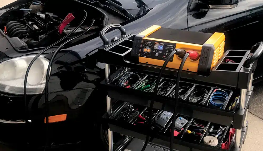
With our PL6100/PL6800 models, we up the power factor considerably, delivering 0-100A on demand. We also add the versatility of adjustable system voltage from 13.1-14.9V, allowing the operator to exactly match the recommended voltage as defined the OEM of the vehicle under service. That precision and power makes these models ideal as reprogramming support tools, plus they add the convenience of 13’ long cables with detachable cable leads for easy access to vehicles of all shapes and sizes.
Have you ever run into a crazy electrical system diagnostic situation like the one Brandon Steckler encountered above? How did you resolve it? Do you have any tips or tricks you’d like to share with our audience? We’d love to hear about it in the comments below.